


Buffer and driver ICs are used to protect signals, increase drive strength, and control loads in electronic circuits. A buffer mainly improves signal isolation, fan-out, and signal integrity, while a driver supplies higher current or voltage for relays, LEDs, MOSFETs, motors, long traces, or communication lines. This article compares buffer vs driver ICs, their types, applications, differential communication uses, and selection factors.

What Is a Buffer/Driver?
A buffer/driver is an electronic circuit used to transfer a signal from one part of a system to another without weakening, delaying, or overloading the source circuit. It helps maintain signal integrity when signals pass through long PCB traces, cables, buses, or multiple connected devices.
A buffer mainly isolates one circuit stage from another and reduces loading effects. A driver increases the current or voltage capability of a signal so low-power control circuits can drive larger loads, faster loads, LEDs, relays, MOSFETs, motors, or communication lines. Although buffers and drivers are different in function, many ICs combine both features in one device.
For example, a microcontroller pin should not drive a motor, relay, or long signal line directly. A driver or buffer handles the electrical load while protecting the controller and keeping the signal stable.
| Item | Buffer | Driver |
|---|---|---|
| Main purpose | Isolates and preserves signal quality | Increases current or voltage drive capability |
| Typical load | Logic inputs, buses, clock lines | MOSFET gates, LEDs, relays, motors, long cables |
| Output strength | Moderate | Higher |
| Main concern | Loading, fan-out, signal integrity | Current, heat, switching speed, protection |
| Common examples | 74HC125, 74HC244, SN74LVC series | ULN2003, MOSFET drivers, RS-485 drivers, motor drivers |
How a Buffer/Driver Works
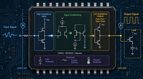
A buffer/driver works by taking an input signal and reproducing it at the output with better strength, stability, and load-driving capability. Inside the device, transistor-based stages process the signal using CMOS, BiCMOS, or bipolar technology depending on the required speed, voltage, and current. The input side usually has high impedance, meaning it draws very little current from the source circuit. This prevents voltage drop, reduces waveform distortion, and keeps the original signal stable.
After receiving the signal, the buffer/driver conditions it and passes it to an output stage designed to handle the load. This output stage is usually low impedance and may use a push-pull or open-drain structure. A push-pull output can source and sink current, which improves fan-out, rise time, fall time, and switching performance. In stronger driver circuits, the output stage can also provide high peak current for capacitive loads such as MOSFET or IGBT gates.
The buffer/driver also isolates the source circuit from the load, so changes in capacitance, current demand, or electrical noise do not directly disturb the original signal. Many modern devices include protection features such as ESD protection, current limiting, and thermal shutdown to improve reliability. In high-speed systems, performance depends on propagation delay, rise time, and fall time because these determine how quickly and accurately the signal can move from input to output.
Types of Buffer and Driver Circuits
Different buffer and driver circuits are designed for specific voltage levels, switching speeds, signal conditions, and load demands. Some are used to clean and strengthen digital logic signals, while others provide the current needed to drive buses, LEDs, motors, power transistors, or high-speed communication paths.
| Type | Main Function | Typical Use | Example Devices |
|---|---|---|---|
| Logic buffer | Strengthens or isolates digital logic signals | MCU outputs, FPGA interfaces, clock lines, digital buses | 74HC125, 74HC244, SN74LVC series |
| Tri-state buffer | Adds HIGH, LOW, and high-impedance output states | Shared buses, memory systems, microprocessor interfaces | 74HC125, 74HC244 |
| Bus driver | Drives larger digital buses or multiple logic inputs | Processor buses, memory interfaces, FPGA signal routing | 74LVC245, 74HC245 |
| Level-shifting buffer | Transfers signals between different logic voltages | 1.8V, 3.3V, and 5V mixed-voltage systems | TXB/TXS series, SN74LVC series |
| Load driver | Allows logic circuits to control higher-current loads | Relays, LEDs, solenoids, small motors | ULN2003, ULN2803 |
| Gate driver | Drives MOSFET, IGBT, GaN, or SiC power switches | Power supplies, motor drives, inverters, EV systems | UCC27511, IR2110, isolated gate drivers |
| Differential driver | Sends signals over noisy or long-distance links | RS-485, CAN, LVDS, Ethernet, industrial networks | MAX485, SN65HVD series |
Digital Logic Buffers
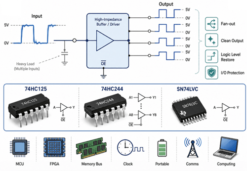
Digital logic buffers reproduce an input signal at the output while reducing the electrical load on the source circuit. They are useful when one MCU, processor, or FPGA pin must drive several logic inputs, long PCB traces, or clock lines.
A logic buffer helps maintain valid HIGH and LOW voltage levels, improves fan-out, and reduces the risk of slow edges or unstable switching. Modern low-voltage logic families are also useful in compact systems where 1.8V, 2.5V, or 3.3V operation is required.
Tri-State Buffers and Bus Drivers
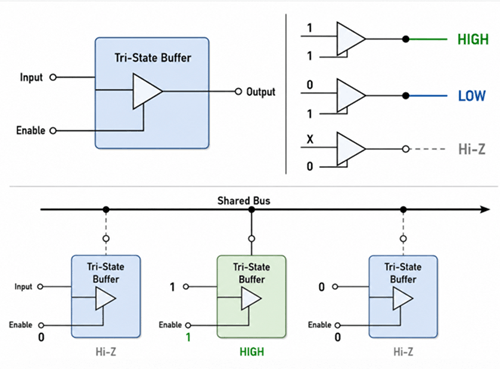
Tri-state buffers provide three output states: logic HIGH, logic LOW, and high impedance. The high-impedance state disconnects the output from the bus, allowing multiple devices to share the same signal line without fighting each other.
Bus drivers are used when a signal must drive many inputs or travel across a wider digital bus. They are common in memory systems, microprocessor interfaces, FPGA boards, and data lines where signal strength and timing must remain stable.
Level-Shifting Buffers
Level-shifting buffers are used when two circuits operate at different logic voltages. For example, a 1.8V sensor may need to communicate with a 3.3V MCU, or a 3.3V controller may need to interface with a 5V peripheral.
Without proper level shifting, the signal may not meet the input threshold of the receiving device, or the higher-voltage side may damage the lower-voltage circuit. A level-shifting buffer helps maintain safe and correct logic communication between mixed-voltage devices.
Load Driver ICs
Load driver ICs allow low-power logic circuits to control higher-current loads. A microcontroller pin cannot directly drive a relay, solenoid, high-brightness LED, or small motor because these loads need more current than the pin can safely provide.
Devices such as ULN2003 and ULN2803 use transistor driver stages to handle higher load current. They are useful in relay boards, LED control, solenoid drive circuits, stepper motor phases, and simple automation systems.
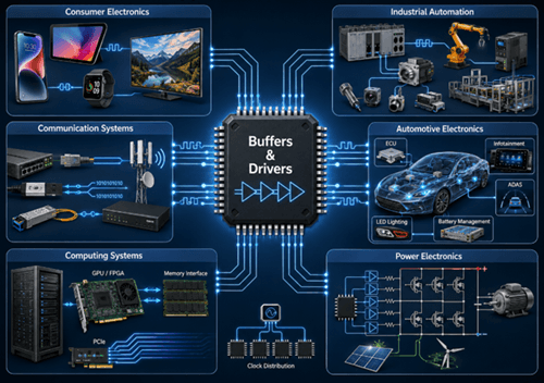
Common Applications of Buffers and Drivers
Buffers and drivers are used when a signal needs stronger drive capability, better isolation, cleaner timing, or safer load control. Different applications use different driver types depending on signal speed, load current, voltage level, and noise environment.
| Application Area | Common Buffer or Driver Type | Why It Is Used |
|---|---|---|
| Microcontroller and GPIO circuits | Logic buffer, level-shifting buffer | Protects MCU pins, improves fan-out, and matches different logic voltage levels |
| FPGA and processor interfaces | Logic buffer, bus driver, clock buffer | Maintains timing accuracy and reduces loading on high-speed digital lines |
| Memory and data buses | Tri-state buffer, bus driver | Allows shared bus control and prevents signal conflict between devices |
| Long PCB traces and cables | Line driver, differential driver | Strengthens signals and reduces noise sensitivity over distance |
| RS-485, CAN, and industrial networks | Differential driver, transceiver | Improves noise rejection and supports reliable communication in harsh environments |
| LED and relay control | Load driver, transistor array | Allows low-power logic signals to control higher-current loads |
| MOSFET and IGBT switching | Gate driver | Provides peak current for fast switching and lower power loss |
| Motor control and power electronics | Motor driver, gate driver | Controls current flow, switching speed, torque, and protection functions |
| Automotive electronics | CAN driver, gate driver, load driver | Supports noisy environments, distributed control, and high-current loads |
| Power supplies and inverters | MOSFET, IGBT, GaN, or SiC gate driver | Improves switching efficiency, thermal performance, and power-stage control |
Communication and Differential Drivers
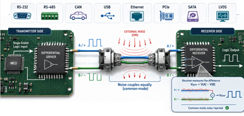
Communication and differential drivers are used when signals must travel through cables, connectors, long PCB traces, or electrically noisy environments. Instead of sending a signal as one voltage referenced to ground, many systems use differential signaling, where the receiver measures the voltage difference between two complementary signal lines.
This method improves noise rejection, reduces common-mode interference, and supports stable data transfer over longer distances or at higher speeds.
Why Differential Drivers Improve Communication
In single-ended signaling, noise on the ground reference or signal line can directly disturb the received voltage. In differential signaling, external noise often couples into both lines in a similar way. Since the receiver reads the difference between the two lines, much of this common noise is rejected. This is why differential drivers are widely used in industrial, automotive, computing, and communication systems.
| Interface | Typical Driver Type | Main Advantage |
|---|---|---|
| RS-485 | Differential line driver | Long-distance and noise-resistant industrial communication |
| CAN | Differential transceiver | Robust vehicle and industrial network communication |
| LVDS | Low-voltage differential driver | High-speed, low-noise board-level signaling |
| USB | Differential signaling driver | Reliable serial data transfer |
| Ethernet | Differential physical layer signaling | Long cable communication and network connectivity |
| PCIe / SATA | High-speed differential drivers | High data rate and controlled signal integrity |
How to Choose a Buffer or Driver IC
Selecting the right buffer or driver IC depends on the signal source, load type, voltage level, switching speed, output current, and PCB environment. A logic buffer is usually used to protect and strengthen signals, while a driver is used when the circuit must control heavier loads, longer traces, cables, MOSFET gates, relays, LEDs, or motors.
How to Select the Right Buffer or Driver IC
| Design Need | Better Choice | What to Check |
|---|---|---|
| One signal drives several logic inputs | Logic buffer | Fan-out, input capacitance, output current |
| Several devices share the same bus | Tri-state buffer | Enable control, high-impedance state, bus conflict risk |
| MCU or FPGA connects to a different voltage level | Level-shifting buffer | Input/output voltage range, logic thresholds |
| Signal travels through a long PCB trace | Bus driver or line driver | Drive strength, propagation delay, termination |
| Signal travels through a cable or noisy environment | Differential driver | RS-485, CAN, LVDS, noise immunity, cable length |
| Logic pin controls a relay, LED, or solenoid | Load driver | Output current, clamp diode, heat dissipation |
| PWM signal controls a MOSFET or IGBT | Gate driver | Peak current, gate voltage, switching speed |
| High-speed clock or data signal needs clean timing | High-speed buffer | Skew, jitter, rise/fall time, layout quality |
For simple logic signals, check voltage compatibility and fan-out first. For high-current or high-speed loads, check output current, thermal rating, propagation delay, switching edge speed, and layout requirements.
Troubleshooting
| Common Problem | Cause | Effect | Solution |
|---|---|---|---|
| Signal ringing and reflections | Improper termination or impedance mismatch | Signal distortion and communication errors | Use proper termination and controlled-impedance routing |
| Driver overheating | Excessive current, poor cooling, or inadequate package rating | Thermal shutdown or device failure | Reduce load current, improve heat dissipation, or select a higher-rated driver |
| Timing errors | Excessive propagation delay, skew, or poor routing | Synchronization failure and data errors | Use faster drivers, match trace lengths, and optimize routing |
| Noise and EMI | Poor grounding, fast edge rates, or weak decoupling | Signal corruption and interference | Improve grounding, shielding, decoupling, and layout separation |
Frequently Asked Questions [FAQ]
Q1. How does fan-out affect buffer or driver selection?
High fan-out increases load capacitance and current demand. A logic buffer helps one signal drive multiple inputs without weak logic levels, slow edges, or timing instability.
Q2. When should a tri-state buffer be used instead of a standard buffer?
Use a tri-state buffer when multiple devices share the same bus. Its high-impedance state disconnects the output and prevents two devices from driving the line at the same time.
Q3. Why do long traces or cables often need line drivers or differential drivers?
Long signal paths add capacitance, noise pickup, impedance mismatch, and signal loss. Line drivers strengthen the signal, while differential drivers improve noise rejection over distance.
Q4. What parameters matter most when choosing a buffer or driver IC?
Check supply voltage, logic thresholds, output current, propagation delay, rise/fall time, output structure, package rating, thermal limits, and protection features.
Q5. Why can the wrong driver cause overheating or timing errors?
A driver with insufficient current, poor thermal margin, or excessive propagation delay may overheat, switch too slowly, distort edges, or cause synchronization errors in high-speed circuits.


