Relays and switches are important components used to control electrical circuits in modern electronic and industrial systems. Although both devices manage current flow, they operate in different ways and are designed for different control requirements.

How Relays and Switches Work
Relays and switches both control the flow of current in an electrical circuit, but they do this in different ways. A switch usually opens or closes a circuit directly, while a relay uses a separate control signal to operate another circuit.
How a Relay Works
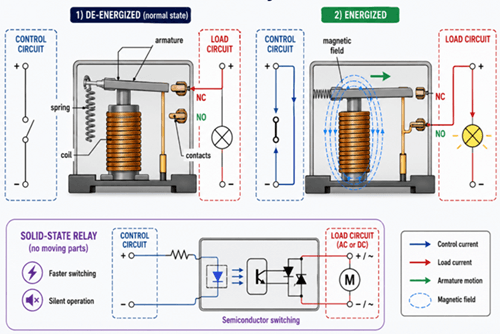
A relay uses a low-power control circuit to switch a separate load circuit. In the de-energized state, the coil is OFF, the armature stays in its normal position, and the contacts remain in their default state. In the figure, the load is connected through the NC contact.
When the coil is energized, it creates a magnetic field that pulls the armature. This moves the contact from NC to NO, changing the load circuit state and allowing the connected device to turn ON or OFF.
This arrangement allows a small control signal to operate a higher-power load while keeping the control circuit and load circuit electrically separated.
The lower part of the figure shows a solid-state relay (SSR). It performs the same switching function without moving contacts, using semiconductor devices instead. Compared with electromechanical relays, SSRs provide faster and quieter switching.
How a Switch Works
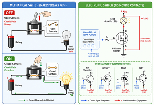
A switch controls current by opening or closing the circuit path. In a mechanical switch, the OFF state keeps the contacts open, so the circuit is broken and the load stays off. In the ON state, the contacts close, completing the path and allowing current to flow to the load.
An electronic switch performs the same control function without moving contacts. It uses a low-power control signal to turn a semiconductor device on or off, such as a MOSFET, BJT, TRIAC, or IGBT. This makes electronic switches useful for fast switching, automatic control, and digital circuit integration.
Relay vs Switch Differences
| Feature | Switch | Relay |
|---|---|---|
| Operation Method | Usually, manual | Electrically controlled |
| Control Style | Direct user control | Automatic or remote control |
| Electrical Isolation | Limited | Strong isolation |
| Load Handling | Direct load switching | Indirect high-load control |
| Automation Capability | Limited | Excellent |
| Switching Speed | Moderate | Moderate to high |
| Complexity | Simple | More complex |
| Cost | Lower | Higher |
| Remote Operation | Limited | Highly suitable |
| Typical Use | Basic power control | Automation and protection |
Common Applications of Relays and Switches
Relay Applications
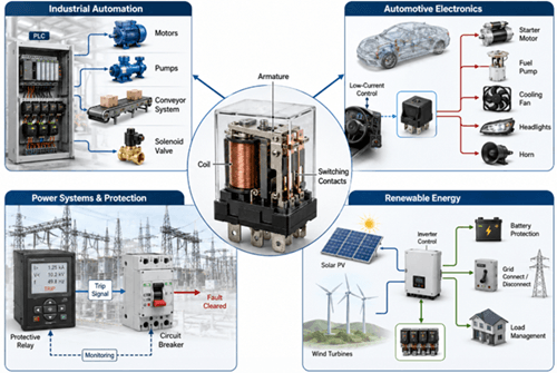
Relays are widely used in systems that require automatic control, electrical isolation, or high-current switching. They allow a low-power control circuit to safely operate a higher-power load, making them useful in industrial, automotive, power, and renewable energy applications.
• In industrial automation, relays are used to control motors, pumps, solenoid valves, conveyor systems, PLC outputs, and factory machinery. They help automate machine operation and allow control systems to switch loads safely and reliably. Relays are also important in industrial safety circuits, emergency shutdown systems, and equipment protection controls.
• In automotive electronics, relays allow low-current switches and control modules to operate high-current vehicle loads. They are commonly used in starter systems, fuel pumps, cooling fans, lighting systems, horns, and battery management systems. This helps protect dashboard switches and electronic control units from carrying heavy current directly.
• In power systems and protection, relays monitor electrical conditions such as overcurrent, voltage faults, thermal overload, and short circuits. When an abnormal condition is detected, protective relays can trigger circuit breakers or disconnect equipment to prevent damage, reduce fire risks, and improve system safety.
• In renewable energy systems, relays are used in solar and wind power equipment for inverter control, battery protection, grid synchronization, and load management. They help manage power flow, protect energy storage systems, and support safe connection or disconnection from the grid.
Switch Applications
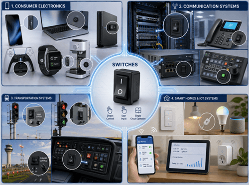
Switches are mainly used where direct control, user input, or simple circuit operation is needed. They open or close circuits to control power, signals, and operating modes in many electrical and electronic systems.
• In consumer electronics, switches are found in computers, smartphones, gaming systems, appliances, and wearable devices. They provide basic power control, mode selection, reset functions, and user input, making devices easier and safer to operate.
• In communication systems, switches are used to control equipment, route signals, and manage connections in telephone systems, network equipment, data centers, and communication racks. They help operators and systems direct signals to the correct path and maintain reliable communication performance.
• In transportation systems, switches are used in railway signaling, airport guidance systems, traffic control equipment, and vehicle control panels. They support safe operation by allowing operators or automated systems to control signals, lights, alarms, and equipment functions.
• In smart homes and IoT systems, modern switches support wireless lighting control, voice assistant integration, remote monitoring, automated scheduling, and energy management. These smart switches allow users to control devices more conveniently while improving energy efficiency and automation.
Types of Relays and Switches
Common Relay Types
| Relay Type | Main Feature | Typical Use |
|---|---|---|
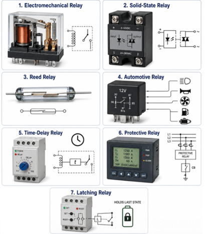
| Electromechanical relay | Uses coil, armature, and physical contacts | General automation, motor control, industrial panels |
| Solid-state relay | Uses semiconductor switching with no moving contacts | Frequent switching, silent operation, temperature control |
| Reed relay | Uses sealed magnetic contacts | Low-current signal switching, test equipment, communication circuits |
| Automotive relay | Designed for vehicle loads and DC power systems | Headlights, horns, fans, fuel pumps, starter circuits |
| Time-delay relay | Switches after a set time delay | Motor starting, sequencing, lighting control, automation timing |
| Protective relay | Detects abnormal electrical conditions | Overcurrent, voltage fault, overload, and short-circuit protection |
| Latching relay | Keeps contact state without continuous coil power | Energy-saving control, remote switching, memory circuits |
Common Switch Types
| Switch Type | Main Feature | Typical Use |
|---|---|---|
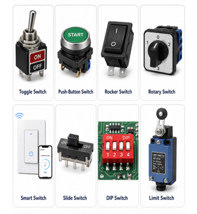
| Toggle switch | Lever-based manual switching | Control panels, machines, equipment power control |
| Push-button switch | Activated by pressing a button | Start/stop circuits, reset buttons, user interfaces |
| Rocker switch | Rocking actuator with clear ON/OFF position | Appliances, power strips, lighting control |
| Rotary switch | Selects between multiple positions | Mode selection, fan control, test instruments |
| Slide switch | Compact sliding contact design | Portable electronics, battery-powered devices |
| DIP switch | Multiple small switches in one package | PCB configuration, address setting, hardware options |
| Limit switch | Detects mechanical position or travel limit | Doors, elevators, conveyors, machine safety, robotics |
| Smart switch | Supports remote or programmable control | Smart homes, IoT systems, building automation |
Relay and Switch Specifications
| Specification | Description | Why It Matters |
|---|---|---|
| Voltage Rating | The maximum voltage the relay or switch can safely handle. | Prevents insulation damage, arcing, and electrical hazards. |
| Current Rating | The maximum current the device can carry or switch safely. | Prevents overheating, contact damage, and overload failure. |
| Contact Configuration | Contact arrangement such as SPST, SPDT, DPST, or DPDT. | Determines how the circuit is controlled or switched. |
| Coil Voltage | The control voltage needed to activate an electromechanical relay. | Ensures the relay operates correctly without coil damage. |
| Switching Speed | Time required for the device to change from the ON/OFF state. | Important for automation, timing, and high-speed switching. |
| Electrical Lifespan | Number of switching cycles under electrical load. | Helps predict service life in real applications. |
| Mechanical Lifespan | Number of switching cycles without electrical load. | Shows durability of moving parts. |
| Dielectric Strength | Ability to withstand voltage between isolated circuits. | Improves safety in high-voltage and industrial systems. |
| Operating Environment | Conditions such as temperature, humidity, dust, vibration, or chemicals. | Ensures reliable operation in harsh environments. |
| IP Rating | Protection level against dust and moisture. | Important for outdoor, wet, or industrial installations. |
| Contact Material | Material used for contacts, such as silver alloy or gold plating. | Affects conductivity, corrosion resistance, and arc resistance. |
| Mounting Type | Installation method such as PCB, DIN rail, panel, socket, or surface mount. | Helps match the device to the system design. |
| Safety Certifications | Standards such as UL, CE, IEC, RoHS, or CSA. | Confirms compliance with safety and quality requirements. |
Safety Comparison Between Relays and Switches
| Safety Aspect | Relay | Switch |
|---|---|---|
| Electrical Isolation | Provides better electrical isolation because the control circuit is separated from the load circuit. This improves safety in high-voltage systems. | Usually connects directly to the load circuit, so users or sensitive electronics may face higher electrical risks if the design lacks proper protection. |
| Arc Suppression and Protection | Relay systems may include flyback diodes, arc suppression circuits, snubber networks, and contact protection systems to reduce contact damage and improve reliability. | Basic switches usually have limited arc suppression unless additional protection components are added. |
| Overload Protection | Protective relays can detect overcurrent, voltage faults, thermal overload, and short circuits, helping prevent equipment damage and fire risks. | Basic switches normally do not detect overload conditions and only open or close the circuit manually or mechanically. |
| Overall Safety Level | Generally safer for high-voltage, high-current, automated, and protection-based applications. | Suitable for simple manual control, but additional protection is needed for high-power or high-risk circuits. |
How to Choose Between a Relay and a Switch
A switch is better for simple direct control. A relay is better when a low-power signal must control a higher-power load, when remote operation is required, or when the control circuit should be isolated from the load circuit.
| Design Condition | Better Choice | Reason |
|---|---|---|
| Simple manual ON/OFF control | Switch | Lower cost, simple wiring, direct user operation |
| MCU, PLC, sensor, or timer controls the load | Relay | A low-power control signal can switch a separate load circuit |
| High-current load such as motor, pump, fan, heater, or solenoid | Relay or contactor | The control circuit does not need to carry the load current directly |
| Low-power device such as small lamp, portable device, or control input | Switch | A relay may add unnecessary cost and complexity |
| Remote or automatic switching is required | Relay | Can be controlled by electronics, sensors, timers, or automation systems |
| Electrical isolation is required | Relay | Separates the control side from the load side |
| Frequent high-speed switching is required | Solid-state relay or electronic switch | No mechanical contacts, faster operation, lower wear |
| User input or mode selection is required | Switch | Easier for direct operation and clear physical control |
| Inductive load is used | Relay with protection | Motors, coils, and solenoids need proper contact rating, flyback diode, MOV, or snubber |
| Harsh environment with dust, moisture, or vibration | Sealed switch or industrial relay | Device rating and enclosure protection become more important |
Check the Load Before Choosing
The load type has the strongest influence on the choice. A resistive load such as a lamp or heater is easier to switch. An inductive load such as a motor, relay coil, solenoid, or transformer creates voltage spikes and contact arcing when switched off.
For inductive loads, use a properly rated relay, contactor, or protected switching device. Add a flyback diode for DC coils, or use an RC snubber or MOV where required.
Check the Control Method
Use a switch when a person directly controls the circuit. Use a relay when the circuit must be controlled by an MCU, PLC, thermostat, sensor, timer, safety controller, or remote signal.
For example, a wall light can use a switch. A motor controlled by a temperature sensor should use a relay or contactor.
Check Isolation and Safety Needs
A relay is preferred when the control circuit and load circuit should stay electrically separated. This is common in high-voltage systems, industrial control panels, automotive circuits, and protection circuits.
A switch can still be used safely in simple low-power circuits, but it must match the load voltage, current, contact type, and installation environment.
Check Speed, Wear, and Maintenance
Mechanical switches and electromechanical relays have moving contacts, so they can wear over time. Contact arcing, oxidation, vibration, and repeated switching can reduce service life.
For fast or frequent switching, use a solid-state relay or electronic switch. For simple manual control, a mechanical switch is often enough.
Quick Selection Rule
Use a switch when the circuit needs simple manual control.
Use a relay when the circuit needs automatic control, remote switching, isolation, or higher-load control.
Use a contactor instead of a small relay when the load is a large motor, compressor, heater, or high-power industrial device.
Common Problems and Troubleshooting
| Problem | Possible Cause | Recommended Solution |
|---|---|---|
| Relay not switching | Coil failure or low control voltage | Check control voltage and coil condition |
| Switch overheating | Excessive current load | Use a properly rated switch |
| Contact arcing | Inductive load switching | Add a flyback diode or snubber circuit |
| Intermittent operation | Worn or contaminated contacts | Replace the damaged device |
| Relay chatter | Unstable power supply | Stabilize control voltage |
| Welded relay contacts | Excessive inrush current or overload | Use a higher-rated relay or surge protection |
| Switch bounce | Mechanical contact vibration | Add debounce circuitry |
| Solid-state relay overheating | Poor heat dissipation | Improve cooling or add a heatsink |
| Unexpected relay triggering | Electrical noise or EMI | Improve grounding and shielding |
| Corroded switch contacts | Moisture or harsh environment | Use sealed switches or a protective enclosure |
Frequently Asked Questions [FAQ]
Q1. When should a relay be used instead of a switch for load control?
Use a relay when a low-power signal from an MCU, PLC, sensor, or timer needs to control a higher-current load, remote circuit, or isolated load circuit.
Q2. Why do inductive loads require extra protection when using relays or switches?
Motors, solenoids, coils, and transformers generate voltage spikes when switched off. Flyback diodes, RC snubbers, MOVs, or properly rated contacts help reduce arcing and contact damage.
Q3. How does electrical isolation affect relay and switch selection?
A relay separates the control circuit from the load circuit, making it better for high-voltage, high-current, automated, or protection-based systems. A switch usually controls the circuit more directly.
Q4. When is a solid-state relay better than an electromechanical relay?
A solid-state relay is better for frequent switching, silent operation, fast response, and reduced contact wear. It still requires attention to leakage current, heat dissipation, and load compatibility.
Q5. What specifications matter most when choosing a relay or switch?
Check voltage rating, current rating, load type, contact configuration, coil voltage, switching speed, electrical lifespan, dielectric strength, mounting type, and operating environment.